Mount/Scope Configuration

Contents
To setup your scope press the Configure Scopes/Mounts button. The dialog below will display as shown here. You can re-size the window if you want to to see all the columns in the table.
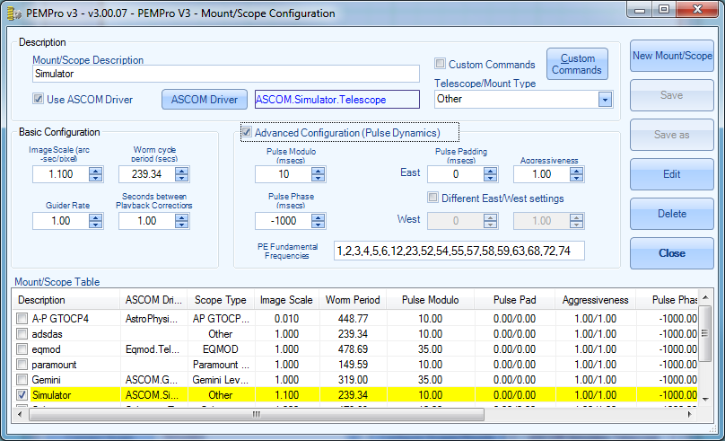
Mount/Scope Description: Enter a text description of your mount or telescope. The description will appear in the drop-down list box to the right of the Connect Scope button on the Setup Page (see Figure 1).
Use ASCOM Driver : Check this box to enable the ASCOM Driver button. Click that button to select your telescope. In most cases you will want to use an ASCOM driver.
NOTE: You do not need to use an ASCOM driver if you have MaximDL V4 or CCDSoft V5 and a connection between your CCD camera and the auto-guider port of your mount.
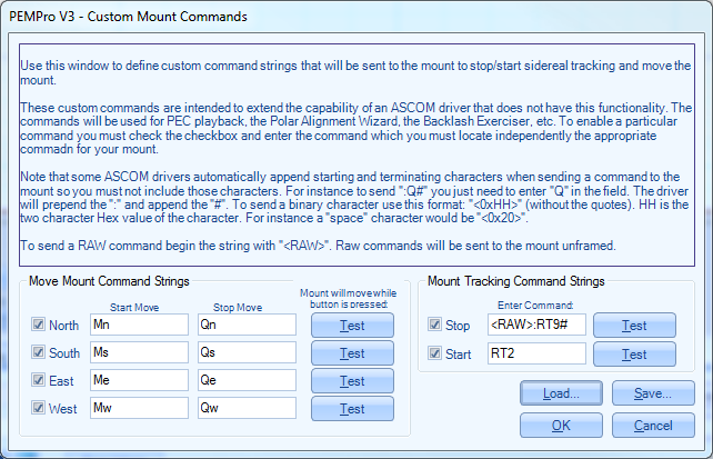
Custom Commands: When checked PEMPro will use the Custom start/stop/move commands as defined by clicking the Custom Commands button. Read this section for more information.
Telescope/Mount Type: Select your telescope type from this drop-down list box. If it is not in the list you will need to enter the worm period in seconds in the Worm Cycle period (secs) numeric text box.
The Mount/Scope Table has an entry for each mount/scope that you define. The text you find in the Descriptions column of this table will be what you see in the drop-down list box to the right of the Connect Scope button of the Setup Page. You can change the current selected scope by clicking its checkbox. Only one scope can be selected at a time so when you select another entry any previously checked entry will be cleared. You can also select a scope/mount by double-clicking its entry.
Items can be loaded into the text fields by clicking its entry in the table with the mouse. If you edited any fields a dialog will pop up asking if you want to save first. The selected entry will be either blue if it has focus or yellow (see figure 2) if the focus is on another control in the dialog.
The following buttons perform actions to the current mount/scope or an entry in the Mount/Scope Table.
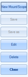
New Mount/Scope : Press to enter a new mount/scope definition. You can also use Save As to create a new scope from an existing entry.
Save : Press this to save your changes.
Save As : Press this to save your changes to a new entry in the table. No two entries in the table are allowed to be the same so this button will not activate until the description is different from any other entry.
Edit : Press this button with a table entry selected will load the entry’s values into the edit controls.
Delete : Pressing this button will delete the item selected in the table. You will be asked to confirm your delete.
Close button: Pressing this button will close the dialog. If you have edited any fields you will be asked if you want to save first.
Mouse Click any table entry to load its values for editing and to select it as the current scope.
Mouse Double Click an entry or selecting a checkmark will define that entry as the current selected scope. That entry will be selected in the drop down list next to the Connect Scope button on the Setup Page when you exit the dialog.
Basic Configuration Parameters
The remaining controls are used when playing back the corrected periodic error. Usually you will only need to modify the Basic Configuration parameters. Making sure these parameters are set correctly is very important to successfully analyzing and maximizing the reduction of a mount’s periodic error.
It is very important to set the basic configuration parameters defined in this section accurately!
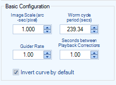
Binned Image Scale: This is the binned image scale of your CCD camera in arc-seconds per pixel. If you have some sort of “image linking” feature in your planetarium program then use it to get the pixel scale.
If you do not have access to a program with image linking there are various programs that you can use to calculate the image scale given the focal length of your scope and the size of the pixels in your CCD camera.
NOTE: The approximate formula for computing pixel scale is: 206.26 * pixel size (micron) / telescope focal length (mm). One thing to remember is that the manufacturer’s claimed focal length is often significantly different than actual.
Worm Cycle Period (secs): This is the primary period, in seconds, of your mount’s worm gear. As with Unbinned Image Scale it is very important to set this accurately. If you select an entry besides Other in the Telescope/Mount Type, then this field is automatically filled in. If you are unsure of your mount’s worm cycle contact the manufacturer.
Guider Rate: This must match the rate that the mount will move in RA in units of sidereal rate. In most cases there is no way for PEMPro to get this from the mount so you must be sure that it is set correctly. In most cases the guide rate is 1.00x sidereal.
Seconds between Playback Corrections: If you have an Astro-Physics mount (Rev D) use 1 second. If you have a Paramount ME try 0.4 seconds. If you have an LX 200, use 1.2 seconds. For other mounts you should try using 1 second.
If you have an Astro-Physics GTOCP3 control box (Rev H firmware or later) then you don’t need to set this parameter because PEMPro can directly program the periodic error correction table in the GTOCP3 controller. This saves time as there is no need to wait for one worm cycle to program the mount. It is also more accurate than the playback method because the mount receives exact movement commands instead of having to measure and convert autoguider or serial command pulses.
Invert curve by default: Some mounts require that the curve be inverted before uploading/playback. Setting this option will automatically invert the curve to the mount.
Advanced Parameters (Pulse Dynamics)
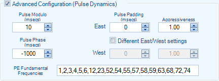
Parameters in this section are optional. Usually you will not need to change these parameters from their defaults.
Pulse Modulo: Some mounts cannot respond to movement commands that are too short in time. This parameter will send pulses (commands to move the mount) in units of this time value in milliseconds. For instance if you set to 40 milliseconds then only pulses of length 40, 80, 120, 160, etc. will be sent (or no pulse at all). The minimum value is 10 milliseconds. Start there and increase the duration if the periodic error was under-corrected.
For Windows 98/ME, you should select a Pulse Modulo that is close to a multiple of 16.7
TIP: You can use the Pulse Test tool to calculate a good minimum value for Pulse Modulo.
Pulse Padding: This adds a fixed number of milliseconds to duration of a pulse in addition to any pulse sent to the mount. Normally this should be 0, however there is a theory that the Meade LX-200’s may need some padding for the pulse to register properly. The range is 0 – 500 milliseconds.
Pulse Phase: This allows you to advance or delay when the pulses are sent to the mount. This allows you to fine tune the timing of the pulses representing the correction curve. The range is -5000 to 5000 milliseconds. Normally leave this at zero, but you can try setting a small negative value to see if that better corrects the mount’s periodic error.
Aggressiveness: This value will be multiplied by the calculated move duration to create an actual duration. Normally this will be set to 1.00 but if your periodic error is being under-corrected you can try increasing this value and retrying. The range is 0.01 to 5.00.
PE Fundamental Frequencies: This is the list of fundamental frequencies defined for this mount. The units are: 1/"worm period".
In almost all mounts are a number of spinning gears that ultimately allow the mount to track at nearly perfect sidereal rate. Because there are always very slight errors in the manufacturing process, every one of those gears is not perfectly round. They are shaped more like an ellipse, but the error is so small you might not be able to actually tell that the gears are not perfectly circular.
Now because each gear is an ellipse it causes the mount to move faster when on the longest diameter of the ellipse and slower on the shortest edge. If you where to chart the motion produced by the gear it would look like a sine wave with a specific duration. Most often the gears also rotate an exact integral number of times in one worm period. This ratio, whether it is an integral or not, is sometimes called a fundamental.
So, if the worm period were exactly 480 seconds and a gear rotates 10 times in each 480 second interval it has a Fundamental of "10" because it would produce a sine wave that repeats 10 times in 480 seconds. In actual time that would mean each rotation of the gear takes 480/10 = 48 seconds.
Most mounts have at least one fundamental that is the period of the worm itself (i.e., the fundamental = 1).