The Graph Area

Contents
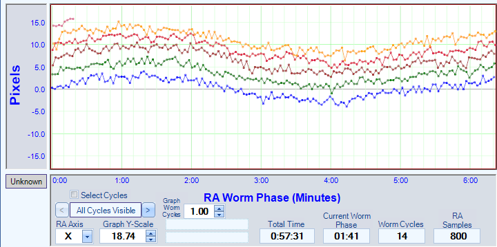
The focal point in PEMPro is the graph. It will provide you with a graphical display of the periodic error data as it is collected. The vertical axis represents the data in either pixels or arc-seconds, depending on the setting "X/Y in arcseconds" on the Acquire Data and Analyze tabs.
The horizontal axis is the mount's Right Ascension Worm Phase. It's width is equal to the worm period of the mount so data at a particular phase of the worm gear is easy to compare across multiple worm cycles.
After each complete cycle of the worm gear the color of the data points will change. In the graph below, drift is evident because each worm cycle migrates down a little in the graph.
The mouse cursor will turn to a cross when positioned over the graph and its position is shown in the fields between Graph Y-Field and Total Time.
All Cycles Visible: Normally PEMPro displays data from all cycles (shown when All Cycles Displayed is shown). Pressing the ">" button will allow you to view consecutive pairs of worm cycles so you can easily see the drift and data.
Each press the ">" or "<" increments or decrements, respectively, the pair of cycles visible. All worm cycles will return to visibility when you decrement down from "1-2 Visible".
Tips: 1. To quickly go back to viewing all cycles double click the "All Cycles Visible" label. 2. To Scale the Y-Scale of the graph, hold down the mouse and drag over the graph area. 3. To shift the Y-Scale coordinates hold the left mouse button down over the "Pixels" area above and move the mouse up or down while keeping the left mouse button pressed. 4. To shift the PEC data up or down, hold the right mouse button down over the "Pixels" area above and move the mouse up or down while keeping the right mouse button pressed. |
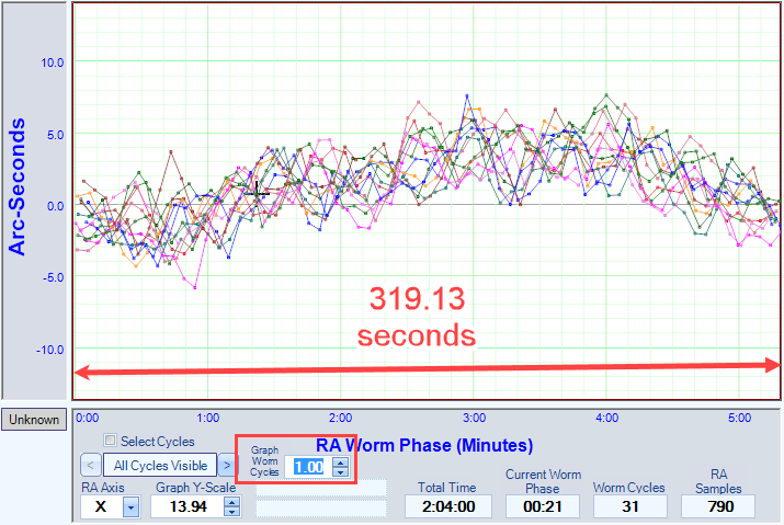
Graph Worm Cycles: This control is visible only on the Acquire Data, Frequency Spectrum, and Analyze tabs. It will change the X-Scale of the graph wraps at a multiple of the worm period. This might be useful if there is a frequency that wraps in an odd number of cycles.
For example, below is a graph of a curve from a mount that has a 7.5x fundamental. Because the 7.5x fundamental doesn't repeat an exact integer of times per worm cycle, it makes the graph look random:
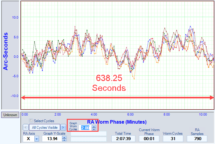
But, when Graph Worm Cycles is set to 2.00, the x-dimension (time) is doubled. Now, since the 7.5x frequency will repeat exactly 15 times in two worm periods the multiple cycles of the graph overlap neatly:
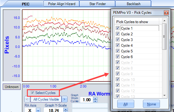
Select Cycles: Selecting this checkbox will bring up a window which will allow you to select which cycles to show on the graph:
RA Axis : The axis of your CCD images that corresponds to the mount’s RA axis. PEMPro does not know which axis is the RA axis so you must define this. You can determine this in a number of ways such as taking a CCD image with the mount tracking turned off. The stars will streak in the direction that is the RA axis. The Y axis is defined as vertical and the X axis horizontal on a CCD image.
Graph Y-Scale : The vertical scale of the graph. You can change this at any time by entering a new scale or using the up/down numeric buttons. Holding one of the buttons down will after a short period cause the increment to repeat automatically. If held even longer the repeat rate will accelerate.
Total Time : The total time PEMPro has been active.
Current Worm Phase : The mount's current Worm Phase. You can double-click this with the mount connected to query the mount to get the phase position again.
Worm Cycles : Number of worm cycles that have been completed since the time the program was started or the Start button was pressed on the Acquire Data page.
RA Samples : Number of images (centroid calculations) PEMPro has taken since the last time the Start button was pressed or that are in a loaded log file.