Gemini Level 4, Gemini-II, Level 5, 6

Contents
These directions apply specifically to the Gemini Level 4 and Gemini-II (Level 5/6) controller. With PEMPro you can:
1. Turn PEC On/Off when connected.
2. Read and display the current and saved PEC tables.
3. Upload a PEC curve to the current or saved PEC tables.
4. Save a curve to a file.
5. Read a curve from a previously saved file.
6. Clear the mount's PEC.
7. Adjust the final curve before sending it to the mount.
Also:
1. When you connect to the mount the worm period and phase are automatically determined from the mount. PEMPro is automatically synchronized to the mount.
2. Whenever you start Acquiring PE data PEMPro automatically synchronizes to the mount. This allows you the freedom to move the mount around without worry of forgetting to re-synchronize.
3. Hovering over the PEC status text box will display a tool tip of the entire PEC status byte. Clicking the text box will update the PEC status.
4. On the Gemini tab the firmware version and guide rate are displayed.
IMPORTANT: You must setup to use JNow instead of J2000 epoch for telescope moves/slews to work as expected.
It is very important to make sure that both the ASCOM driver and the mount hand paddle are set for JNow, not J2000.
So, to edit the Gemini ASCOM settings in PEMPro click Settings->Edit ASCOM Driver Settings...
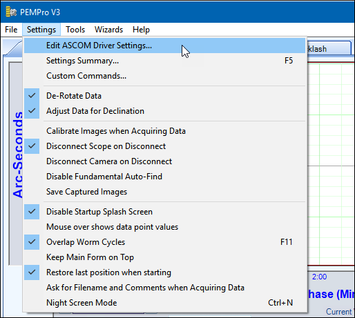
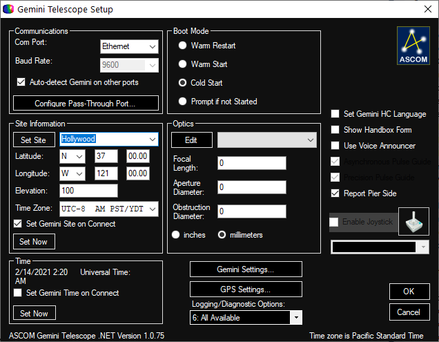
PEMPro will hide itself temporarily and the ASCOM Gemini Controller Setup dialog will pop up.
IMPORTANT POINT 1 : If you are using the old Gemini ASCOM driver (not the new .Net version) it may take up to 5 minutes for the Gemini dialog to appear if the serial COM port is set to a port not connected to the mount! Please be patient and wait for the dialog to appear. During this time PEMPro will not be visible but it is still running in the background and will reappear when you exit the ASCOM dialog. |
IMPORTANT POINT 2 : Once you are in the driver settings dialog make sure the important settings like the Mount Type and Site Information are set correctly. If you fail to set up the ASCOM driver to match your mount type and other settings then the Gemini Controller's settings in your mount may be overwritten by whatever the default settings of the ASCOM driver happen to be. |
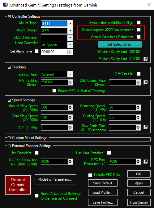
Lastly, go into the "Advanced Setup" page and uncheck "Gemini expects J2000 co-ordinates" and "Gemini Calculates Refraction". See picture below:
Then confirm the correct setting using the hand pad (Setup, Communications). Until you change the driver settings, you may find that your hand pad settings do not stick between sessions.
Basic Steps to use PEMPro with your Gemini Level 4 and Gemini II (Levels 5,6) controlled Mount
You must follow these basic steps to use PEMPro:
1. Use the mount wizard to create an instance of a Gemini Level 4 or Gemini II mount in PEMPro. You only need to do this step once.
2. Each time before acquiring periodic error data you should run the Calibration Wizard.
3. Acquire 5-6 worm cycles of periodic error data with PEC turned off.
4. Create a PE curve.
5. Adjust curve if needed and upload the curve directly to your Gemini
6. Check that PEC is reduced by turning PEC on and acquiring a couple worm cycles of data.
Each of these steps is explained in more detail below:
Setup Gemini mount with the Mount Wizard
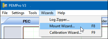
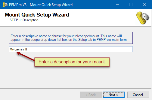
The first thing you must do is to create an instance of a Gemini Mount in PEMPro. The easiest way to do that is with the Mount Wizard. Press F8 or go to the Wizards Menu and select Mount Wizard...
When the Mount Wizard comes up enter a unique name for your mount. When you exit the Mount Setup wizard the name you type will appear in drop down list box to the right of the Connect Scope button on PEMPro's Setup tab.
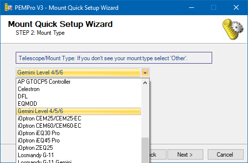
Press Next> to continue. Select Gemini Level 4/5/6 in the drop down list in Step 2. Click Next> to continue.
The last step will automatically select the ASCOM.GeminiTelescope.Telescope driver:
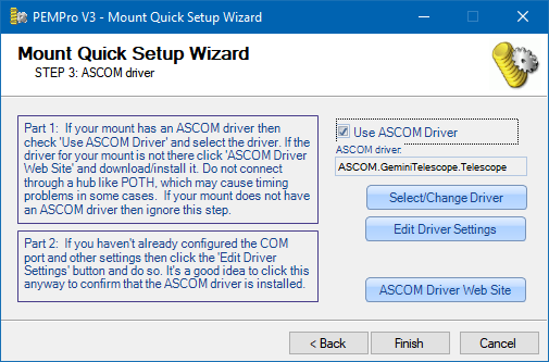
The next thing you should do is verify your ASCOM driver is setup is OK by clicking Edit Driver Settings.
Run the Calibration Wizard before acquiring data
Once every session, before acquiring periodic data, you should run the Calibration Wizard. The Calibration Wizard sets all of the important parameters used by PEMPro to accurately calculate periodic error. Note that you don't need to run this wizard if you are analyzing data previously collected.
Some of the settings established include:
•Telescope declination
•Camera tilt angle
•Which axis of the camera corresponds to Right ascension
•Image Scale
•Telescope movement direction
Before starting the Calibration Wizard you should center a 6th-8th magnitude star in the center of your CCD camera. The star should be just west of due South and at 0 degrees declination or higher if you are in the Northern hemisphere.
If you are in the Southern Hemisphere, the star should be just West of due North and 0 degrees declination or lower. In either case it is best to pick a star within 45 degrees of the celestial equator (in Northern hemisphere: 0 < declination < +45, in Southern Hemisphere: 0 > declination > -45).
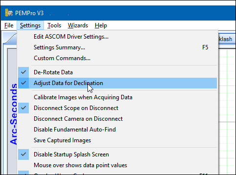
Make sure that Adjust Data for Declination is checked in the Settings Menu. While you are at it also make sure that De-Rotate Data is also checked. If either is not checked then enable them.
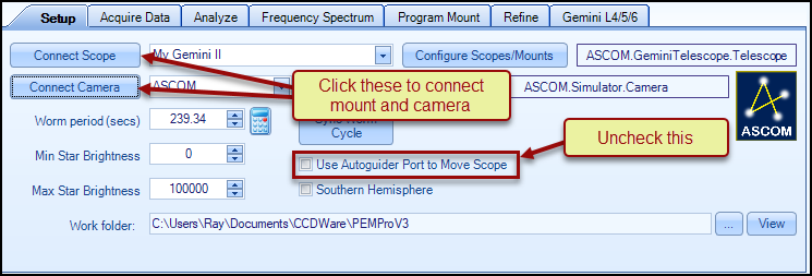
Connect to your Gemini equipped telescope by pressing the Connect Scope button on PEMPro's Setup tab. Select your camera control program and connect to your CCD camera by pressing the Connect Camera button. Also, make sure that Use Autoguider Port to Move Scope is unchecked.
To active the Calibration Wizard select its menu option:
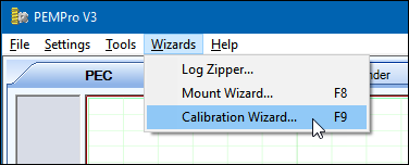
If you are not familiar with the steps of the Calibration Wizard then you can find how to use it here.
Acquiring Data
Make sure that you are connected to the mount and the CCD camera as described above. You will know you are connected when the scope and camera drop down list boxes are grayed out and the buttons say Disconnect Scope and Disconnect Camera as shown here:
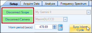
Also make sure that ASCOM.GeminiTelescope.Telescope appears in the text box next to Configure Scope/Mounts.

Important: Do not connect to the Gemini through an ASCOM hub such as POTH. Make sure that the text field to the left of the Configure Scopes/Mounts button says ASCOM.GeminiTelescope.Telescope. If not, press Configure Scopes/Mounts and change the ASCOM driver to be the native Gemini driver. |
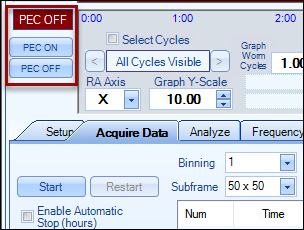
One other thing you will want to do is to make sure PEC is off. PEMPro has convenient buttons to turn the PEC on/off. If PEC is on then simply press the PEC OFF button.
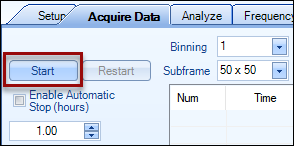
Then click the Acquire Data tab and press the Start button. If you have Ask for Filename and Comments when Acquiring Data checked in the Settings menu, you will have an opportunity to change the default filename and add optional comments to the file.
Before PEMPro takes any images it automatically queries the mount for the current worm position and synchronizes the data that it is about to collect to the mount's worm phase. This means that you can freely move the mount before acquiring data without the risk of forgetting to synchronize PEMPro to the mount.
Now, just sit back and let PEMPro collect 5-6 cycles of periodic data. The horizontal axis of the graph is worm phase and the vertical axis is the measured PEC. After each worm cycle the color of the data will change.
Click Stop when you are done collecting data. If you have Ask for Filename and Comments when Acquiring Data checked in the Settings menu, you will have a final opportunity to add comments to the file or delete the log file and start over. If you don't delete the file you will be prompted to go directly into the create curve dialog:
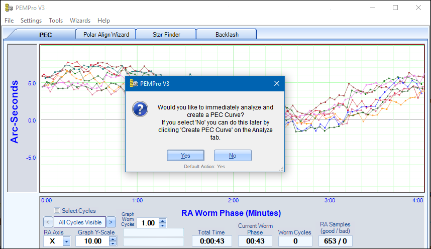
Click Yes to continue.
Create a PE Curve
You can create a PE correction curve immediately after acquiring data or use the log file created in a previous session. PEMPro places all log files in the directory specified in the Logs and Images Dir field on the Setup tab of PEMPro's main window.
When the create PE Curve dialog opens it may take a few seconds to calculate an optimum curve. In most cases you won't need to do any modifications to the curve. Advanced users may wish to add or remove fundamental frequencies to see how that effects the curve's fit, the measure of which is the RMS Error in the upper right of the dialog.
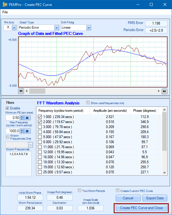
Before leaving this dialog take a moment to check that the Worm Period, Image Roll, Declination, and Image Scale look correct. If anything looks wrong click Cancel and go back to the Setup and Calibration Wizard to setup the parameters again. Otherwise press Create PE Profile and Close if you are satisfied with the curve.
Adjust Curve and upload to the mount
After the Create PE Curve dialog closes in the previous step, PEMPro will automatically switch to the Gemini L4/5 tab and ask if you want to upload to the mount. If you click Yes the curve is immediately uploaded to the mount and you are done!
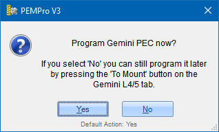
However, if you are an advanced user you may to click No so that you can first adjust the settings in the Curve Tweaking group. Controls on the Gemini L4/5 tab are explained below.
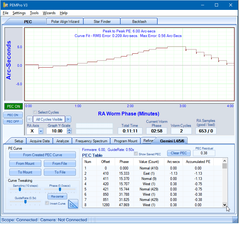
At the top of the graph information about the curve is displayed and dynamically updated if you use any of the controls in the Curve Tweaking section.
Peak to Peak PE: This is the total periodic error of the curve.
Curve Fit - RMS Error: This is a measure of how well the curve to be uploaded to the mount matches the optimized curve that PEMPro created. The lower this number the better.
Max Error: This is the maximum deviation at any point in the curve to be uploaded from the optimized curve that PEMPro created.
Check Corrected PEC
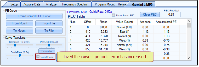
After you upload the new PE correction curve you will want to turn PEC On and acquire at least 2 worm cycles of data. If you see that the periodic error is worse than before you can go back to the Gemini L4/5 tab and check the Invert Curve check box and then click To Mount to send the curve to the mount again. Then start the acquire data again. The mount's periodic error should be significantly reduced.
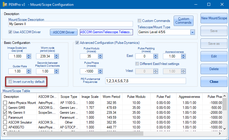
NOTE: you can also force the curve to be always inverted from the Mount Configuration dialog window:
After checking the corrected periodic error of the mount, if you find that you want to try for further improvement you can use the Refine feature.
Gemini L4/5/6 Tab features
VERY Important: The Gemini Level 4/ Gemini II (Level 5 or 6) PEC data is directly tied to the guide rate. The Gemini firmware supports 0.2x and 0.8x guide rates - 0.5x is recommended. If you program PEC to the mount then you use a different guide rate than what was in effect when PEC was programmed the PEC data will no longer be valid and will need to be reprogrammed (or guide rate returned to the original rate). |
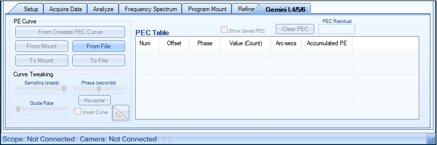
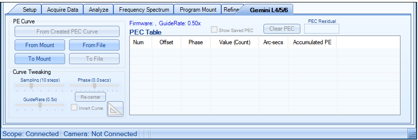
Below is the Gemini L4/5/6 tab before connecting to the mount. All the buttons and controls are disabled except the From File button and the Show Saved PEC checkbox. If you click From File you can load in a previously saved PEC curve. The table will then fill with entries from the file and a graph of the curve will display.
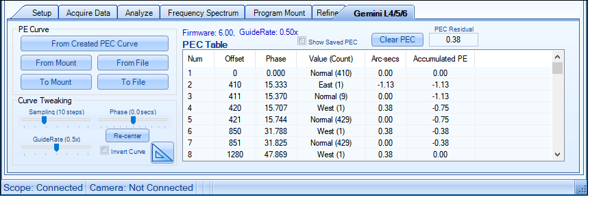
Once PEMPro is connected to the mount on the Setup tab, the From Mount and To Mount buttons are enabled. Also note that the firmware and guide rate are also displayed.
Once a curve has been created in the Create PE Curve dialog, the From Created PE Curve button and all of the controls in the Curve Tweaking section are enabled.
Here is a summary of all of the controls:
From Created PE Curve: loads a PE curve that has just been created or loaded.
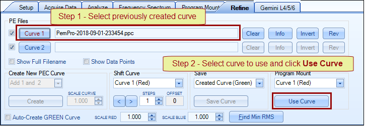
A previously created curve (*.ppc) can be loaded through the Refine page. Just load a curve with the Curve 1 button then go to the Program Mount section and press Use Curve. You can then import the curve to the Gemini L4/5 tab by pressing the From Created PE Curve button:
From Mount: loads the current and saved PEC curves from the mount. You can toggle between the current and saved PEC curves with the Show Saved PEC checkbox.
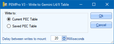
To Mount: This will save the currently displayed PEC curve to the mount's Current PEC or Saved PEC table. Select the table and press OK to program the table or Cancel to quit without saving.
If you have a fast serial port you may want to set the Delay between writes to mount to 0 milliseconds. The default is 20 milliseconds but the range is 0-100 milliseconds. In general, if any error message pops up when writing to the mount then try increasing this delay value.
From File: will load a previously saved PEC file. Gemini PEC files have the extension ".gpe" and are simple ASCII text files.
To File: will save the currently displayed PEC data to a file. Gemini PEC files have the extension ".gpe" and are simple ASCII text files.
Show Saved PEC: if the From Mount button was pressed this will toggle the displayed curve between the Current Curve and the Saved Curve.
Clear PEC: this will clear the current PEC curve.
Sampling: this controls the sampling size that PEMPro uses to create the curve. The lower the value the finer the resolution but the more table entries that are created (longer upload/download times for PEC curves). The default is 10 steps but lowering to 1 might produce a slightly more accurate curve.
VERY Important (repeated from above): The PEC data is directly tied to the guide rate. 0.2X through 0.8X guide rates are supported by the firmware. If you program PEC to the mount then you use a different guide rate than what was in effect when PEC was programmed the PEC data will no longer be valid and will need to be reprogrammed (or guide rate returned to the original rate). |
GuideRate: this controls the guide rate that the PEC is calculated for. When the curve is uploaded to the mount the guide rate (and the PEC guide rate) are set to this rate automatically. In general the lower the guide rate the more accurate the PEC curve at the expense of a limited correction speed.
Phase: this allows you to slightly alter the phase of the curve (up to 5 seconds forward or backward). Usually this is set to 0 but slightly adjusting this value (usually to the negative) will compensate for any timing errors in the acquired data caused by camera download times.
Re-center: this will reset the Phase to 0.0. After adjusting Phase it is sometimes hard to reset it to 0. By the way when one of the track bar controls is selected the left and right arrow keys can be used to adjust the control one step at a time.
Invert Curve: Inverts the displayed curve. Use this to flip the curve if the periodic error of the mount is doubled (after correction) instead of reduced.
PEC Drift Compensation
There's been a lot of issues with RA drift increasing once PEC has been loaded. The current version of PEMPro has some features that can allow you to correct excessive drift should it occur after uploading a PEC curve. In particular it can automatically measure and remove drift from the periodic error curve.
.
Before using this feature you must acquire data with PEC disabled or load a previously created PEC curve. If you don't have a proper PEC curve loaded the automatic drift removal will not work correctly. When a curve is loaded you should see the statistics reported at the top of the graph like in the above picture. Also, after you upload your PEC curve to make sure periodic error is reduced. If periodic error increased, invert the curve and upload again.
The basic procedure to use the automatic drift correction is:
1. Make sure you are connected to both the Gemini and your camera. You can do that on the Setup tab.
2. Slew your mount to near 0 declination and just West of the meridian. If there is an obstruction at 0 declination you can start at a higher declination, up to 60 degrees in the North, or -60 in the Southern Hemisphere.
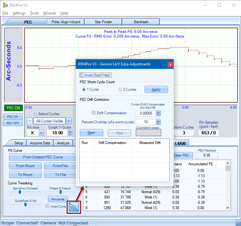
2. To start click the tool button to access the "Gemini L4/II Extra Adjustments" dialog.
3. If not already 0 set the Current Drift Compensation to "0".
4. Set the Percent overlap to 10% or greater. This defines how much overlap in a worm cycle will be captured and used for the drift calculation. For example, if the worm period is about 240 seconds 10% overlap would be an extra 24 seconds, or 264 seconds total per iteration.
5. Click "Start" and watch to make sure that the star doesn't fade or drift off the CCD. PEMPro should notify you if this happens.
6. After each iteration PEMPro will automatically make an adjustment to the drift compensation value and upload it to the Gemini. PEMPro will then start a new iteration. Once drift has been significantly reduced click Stop.
If you encounter problems with the Automatic Drift Compensation feature post your "Drift" log file to the PEMPro CCDWare forum. You'll find the drift log files in the same directory as your normal log files. Click the "View" button on PEMPro's Setup tab to open a Windows Explorer instance in the logs directory.
Other NOTES: Invert East/West - Allows you to reverse the East/West direction, which in case PEMPro has it wrong, would cause drift. Reports have not indicated that this needs to be checked, so it is best to leave it unchecked. Drift Compensation - When manually checked the drift adjustment value will be applied to the active curve in the main dialog. The automatic procedure will enable this option when you click. Note that if you manually use this option to adjust the drift compensation value it just affects the curve displayed in PEMPro. You must still upload the curve to the mount by clicking To Mount before the mount will be able to use the drift compensation value. |