Using the Meridian Tracking Limits Explorer

Contents
Warning: Please take special note of the following: •The Meridian Limits, are primarily tracking limits in the west, and counterweight-up slewing guides for APCC's advanced slew logic in the east. They will NOT prevent you from slewing into your pier with an incorrect slew, or from running into the pier with direction buttons. •DO NOT use any other method for setting a meridian delay while you are using the meridian limits. When properly configured, the APCC meridian tracking limit logic will maintain the correct meridian delay in the system. •Allow the "Counterweight Up Slews within: East Limits" feature (see Meridian Limits - Operation) to safely slew your mount into a meridian advanced position east of the meridian. Do not try to "outsmart" the system and finagle this yourself. |
Getting Started
The Meridian Tracking Limits Explorer allows you to create a detailed limits curve using relatively simple steps. The idea is to slowly slew the scope while watching it at each declination value until it is about to hit the pier. The hour angle at which pier collision is about to occur is saved for each declination value that you try. The Meridian limit between sampled declination values is interpolated between measured values. If there is no measured value or a declination higher or lower than a measure declination then it is assumed to be zero (that is, the Meridian). Take note of the following:
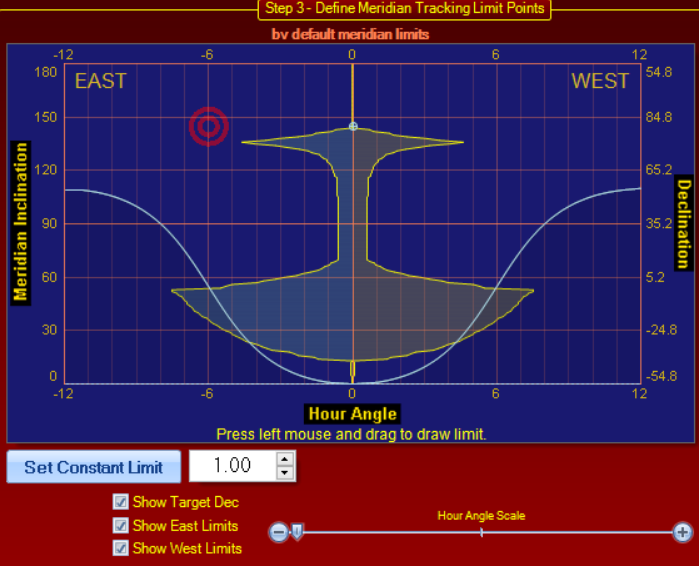
•The Meridian Tracking Limits employ the concept of the Meridian Inclination. Meridian inclination is a universal concept that is not affected by a persons's latitude. Meridian inclinations, as one might expect, are measured along the meridian. With meridian inclination, the zero point is the horizon directly opposite the pole, and a meridian inclination of 180 is the horizon point directly below the pole.
oIn the north, the zero meridian angle has a declination of: –(90 – Latitude). In the south it is: –(–90 – Latitude)
oThe zenith has a meridian inclination of 90. The 90 degree meridian inclination has a declination equal to your latitude.
oCurrently, the meridian limits can only be defined up to your pole.
•It is advisable to have your horizon limits established before you try to set your meridian limits. You will want to take note of the altitude value for the horizon limit opposite your pole: Az = 180 for the northern hemisphere, Az = 0/360 for those "down under." Note that the altitude at these azimuth values will be equivalent to the meridian inclination.
oNOTE: Although you want to have set your horizon limits, be sure you have disabled them by unchecking the "Enable Horizon Tracking Limits" check box in the horizons tab before you begin your Explorer mapping.
•Make sure that your equipment is fully installed and oriented as it will be for usage. If you have a rotator for imaging equipment, be aware that you will want to always rotate the imaging system into its worst case position with respect to the pier.
•Make sure that you do NOT have a meridian delay in effect!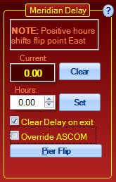 Click the "Clear" button. "Current" should be set to "0.00."
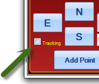
•Uncheck the Tracking check box in the lower left corner of the Explorer window if it is checked. (Unchecked is the default.)
Your First Point on a Side
Your first point on each side of the mount will be handled a bit differently from the subsequent points on that side.
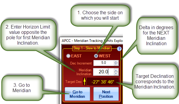
1.Begin by deciding which side of the mount you wish to map first. Click the appropriate button in the upper left of the Step 1 Box. It does not matter which side you do first. Many people will start with the West limits since the tracking direction is westward. However, don't simply forget about the East limits. As described earlier in the Meridian Tab section, you can allow the mount to automatically start in safe positions in the east with the CW up for "flip-free" imaging through the meridian!
2.Enter the altitude value from your horizon limits as described above into the Meridian Inclination field. Observe that the Target Declination will change to reflect the newly entered Meridian Inclination value. Please note that this value does NOT yet include the Dec. Increment.
3.Click the "Go to Meridian" button. The mount will slew to the meridian on the chosen pier side at the entered meridian inclination.
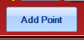
4.For this first point, DO NOT move the mount further with the E-W buttons. Instead, simply click the "Add Point" button at the bottom of the Step 2 box.
Subsequent Points on a Side
Now that you have set your starting point at the horizon opposite your pole, you are ready to map your meridian limits in earnest!
1.Select the declination increment you wish to use at the start. This is the number of degrees delta in declination to slew with each click of the Next Position button. For most people, the limits starting out can be rather coarse, in the 5 to 10 degree range. (The max is 20°) You may want to tighten this up as you get closer to the pier.
2.Click the "Next Position" button. 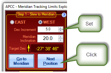
Once you click the "Next Position" button:
a.The mount will begin to slew;
b.The Meridian Inclination will update;
c.And the Target Dec. will also update.
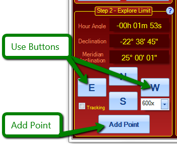
3.During the slew to the "Next Position," the direction buttons will be grayed out. Once they become available, move the mount east or west, depending on the side you are mapping, until you either reach the pier, or point to the horizon. You can use any button control that you have available, but the most convenient are usually either the buttons right there in the "Step 2 - Explore Limit" box, or else the buttons on the keypad. We have found that it is often quickest and easiest to use the direction buttons in the Meridian Tracking Limits Explorer at higher speed (600x or 1200x) to get close, and then to finish with the keypad at 64x. The keypad allows you to stand where you can see the scope and pier more clearly. Allow yourself a bit of "safety margin," but since these are tracking limits, you don't need a lot.
4.Decide on next Dec Increment in the Step 1 - Slew to Meridian box. Change if necessary.
5.Return to step #2 - Next Position - above.
Some Hints:
•In general, the North and South buttons are not used, but they can come in handy if an obstruction is just narrowly missed at a given point. The subsequent Dec Increment will be calculated from the new, adjusted Dec. value, not from the original value to which the mount slewed.
•If you are taking your limit mapping all the way to the pole, be sure to compare the current declination to the declination increment. This is explained further in the next heading - Finishing at the Pole.
Finishing at the Pole
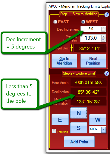
Meridian Tracking Limits are not currently defined below the pole in APCC. Future releases may add this feature if it is demanded. Because the program cannot define the limits below the pole, you must stop your mapping just before the pole. See the screen shot below:
There are two options at this point.
1.You can skip this last small increment and go to the other side, or finish if this is the second side already. See Below:
2.You can enter a last "adjusted" increment. In the example from the screen shot above, I would enter an increment of 4.3° (4° 18'). { Note that 4.4° (4° 24') would overshoot the pole by 42". }
After the Last Point on a Side When you have added your last point for the side, there are several options:
•If this is the first side of the mapping, return to step 1 of the "Your First Point on a Side" section.
oAt step 1, choose the other side, and then proceed with the rest of the "Your First Point on a Side" instructions. Continue as before.
•If this is the first side of the mapping, you can map the other side by "reflection." Reflecting will precisely copy the mirror image of the mapping you just completed onto the other side.
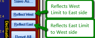
Note that the button is for the side being reflected, not the side to which you are reflecting!
Also Note: Reflected mappings can be further edited and refined using any of the methods for mapping described in these instructions.
•Save the Meridian Limits File ( *.mlm) The mapping you create will automatically be kept in a file named Default.mlm. You will not lose it, but any changes you make to a limit mapping will overwrite the Default.mlm file with the changed data. Default.mlm is always the currently loaded limit file in whatever edit condition you have placed it. If you have invested the time to do a detailed mapping, take the time to save it so that you can retrieve it later. Saved files can always be loaded and edited or changed later and re-saved.
•Some additional notes:
oThere is no requirement that you start at the horizon away from your pole and then work your way poleward. You can even set negative increments to go backwards. However, we have found that after trying various methods of setting up these limits, starting at the horizon away from the pole has become the method we prefer ourselves.
oYou do not need to carry your limits all the way to the pole. Remember, however, that zero limit values will not allow you any tracking past the meridian at those declinations. An easy and quick way around this is to simply carry the "worst case" value at the pier the rest of the way poleward in one jump.