Connection Group Box

Contents
In this group box you can set up the connection to the mount via a COM port, or if you have a GTOCP4/GTOCP5, also via Ethernet or WiFi.
Below are some images showing various states of configuration and connection:
Using GTOCP4/GTOCP5 with Ethernet Those of you with the GTOCP4/GTOCP5 Servo Control Box now have the option of connecting directly with Ethernet or WiFi. Ethernet connections can either be direct peer-to-peer connections (cable direct from the computer to the GTOCP4/GTOCP5) or they can be through a local area network (LAN). In a similar manner, the GTOCP4/GTOCP5 can have its WiFi configured as an Access Point for direct connection from a WiFi enabled PC, or it can join your established WiFi network in Station Mode. See IP connections below. |
Connection Types:
You have two primary choices when connecting your computer to your mount: Serial (USB), UDP, and TCP. Serial requires a USB connection to the mount, while UDP and TCP require an ethernet or WiFi connection
The following sections describe how to connect APCC to your mount based on your preferred connection choice
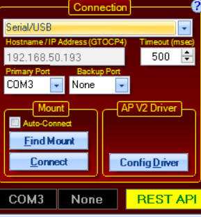
Serial/USB
When you put APCC in serial port mode, the Primary and Backup COM Port drop down list boxes will become available and the Hostname/IP Address field will become disabled.
The USB connection on the GTOCP4/GTOCP5 is treated as a normal serial port as far as APCC or the AP V2 driver is concerned. If you are connecting with USB, simply follow the instructions for COM ports below as if it were a serial port. Please note that you MUST first install the FTDI Driver onto your computer for USB to operate properly. Note also that the FTDI USB to serial devices are all uniquely serialized. Each one will be assigned its own COM port that will be remembered through power-cycles.
Please check the Astro-Physics Software Updates page for links to the latest FTDI drivers
Primary COM Port: The list of serial ports that were detected on the computer will be displayed in this drop down list box. Select the default COM port that APCC will use when the Connect to Port button is pressed.
Find Mount: If you aren't sure of the mount's COM port number, you can also click the Find Mount button which will scan your serial (COM) ports.

It will scan your serial ports and if it finds a mount it will prompt if you wish to use the found COM port:
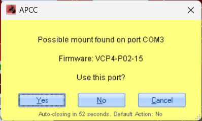
You can choose No to continue searching other ports (for example, if you have multiple mounts connected to the same computer). If it exhausts all ports and does not find a mount, it will report the COM ports it tried.
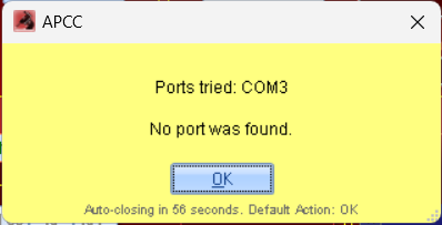
At this point you will need to investigate the physical mount connection (USB cable) and/or confirm the proper FTDI drivers are installed.
Note for GTOCP3 users: Be sure that your serial cable is connected to the top RS-232 port on the GTOCP3 control box.
GTOCP4/5 users: You do not need to show any preference between the top, bottom and USB ports. All should perform equally well.
Backup COM Port: If you choose to, you can select a secondary COM port for APCC to try if the primary COM port has a problem for any reason. To use this feature you will need to use both ports on the control box and will need a second USB/serial port converter. This adds an extra layer of reliability in case the primary USB/serial port converter fails. The backup port will be the bottom COM port of the GTOCP3 control box. Ideally, this should be a physically separate serial port from the primary port. If you simply use another port on a single multi-port USB to serial converter, and the converter or USB connection fails, you will lose both ports and gain nothing. If you use a second USB to serial converter that is attached to a different USB port on the computer, you are much more likely to survive a COMs problem.
Timeout: Here you can set the timeout in milliseconds for responses from the mount. In Ethernet or WiFi mode, the ideal timeout can be quite variable depending on the rest of your system. We suggest starting out at 50 ms for cabled Ethernet connections, and try 100 - 200 ms for WiFi networks. For COM ports - whether serial or USB, usually 100 or 200 ms is good enough. However, sometimes it may be necessary to increase this value to 300, 400 or even 500 ms. (Note the difference between this recommended setting and the longer recommendation for the AP V2 ASCOM Driver when it is used through APCC's Virtual Ports.)
UDP or TCP (LAN or WiFi)
UDP or TCP?
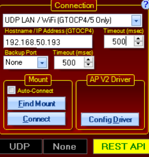
UDP LAN / WiFi (GTOCP4/GTOCP5 Only): UDP is a lightweight connectionless protocol that usually will be the best choice when connected to the CP4 with a reliable hard-wired connection. It can also be used for WiFi connections but the UDP protocol does not guarantee delivery of packets. APCC tries to resend a command one time if it gets no response, then it will report an error. To check the error count click the "Comm Events" button in APCC' status bar. You can only click this button if there are errors.
Note that when this option is selected the two COM Port's drop-down boxes will become inactive, and the Hostname/IP Address box will become active. The Hostname/IP Address box is not a drop-down box, but requires the entry of either the appropriate Hostname or IP address. It is always preferable to use the true IP address, but it is generally easier to use the Hostname. Clicking the Find Mount button will broadcast a request out to your local network. Any GTOCP4/GTOCP5 that gets the broadcast should and respond.
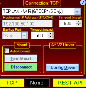
TCP LAN / WiFi (GTOCP4/GTOCP5 Only): TCP is a more robust connection-oriented protocol. It has considerably more overhead than UDP both in system and network resources but it is generally more reliable than UDP. It can be used for both wired and WiFi connections. In general it is better to use the lighter weight UDP protocol unless you start to see a considerable number of errors.
Note that when one of these options are selected the Hostname/IP Address box will become active and the two COM Port's drop-down boxes will become inactive. The Hostname/IP Address box is not a drop-down box, but requires the entry of either the appropriate Hostname or IP address. It is always preferable to use the true IP address, but the Hostname can also be used as an alternative. Clicking the Find Mount button will broadcast a request out to your local network. Any GTOCP4/GTOCP5 that gets the broadcast should and respond and be listed.
Note that a GTO controller's wired Ethernet Hostname and a wireless WiFi Hostname will be different from each other. In general, unless you have changed them the names will all end in the numeric portion of the GTOCP4/GTOCP5 serial number (without the leading zeros if there are any). For example, the control box with serial number: CP4-0456 would have a cabled Ethernet Hostname of: GTOCP4_456. The WiFi Hostname would be GTO_WIFI_456.
IP addresses can be obtained easily from your GTOCP4/5's main web page. Use the handy Find Mounts utility app (look under Utilities and download Find Mounts) to find the relevant information and open the GTOCP4/5's internal web page. Note that network-based IP addresses are subject to changes, whereas the peer-to-peer and access point IP addresses remain unchanged unless you change them.
Find GTOCP4/5 button: Clicking the Find Mount button will open a new window and send out a broadcast to find a GTOCP4/GTOCP5 on the LAN (or WiFi).
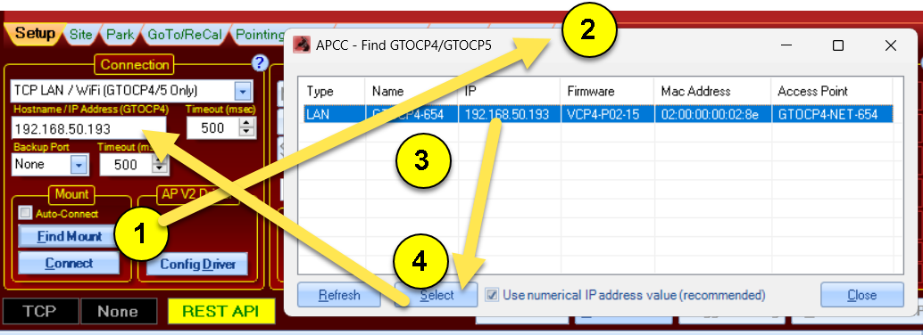
Use the following steps as indicated in the picture above:
1) Click the Find Mount Button
2) The Find GTOCP4/GTOCP5 window will open and report and control boxes that are found.
3) Click the entry for the mount that you want to connect to. This will enable the Select button.
4) Click the Select button. This will close the Find Mount feature and will copy the mount connection information into the Hostname/IP address field
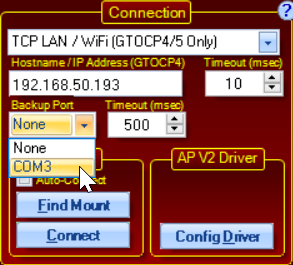
Backup COM Port: You can also optionally setup a backup COM port for APCC to try if your TCP or UDP has a problem for any reason.This adds an extra layer of reliability in case the primary ethernet connection fails. To use this feature you will need to have a USB cable connected to your mount You can specify the backup port in the same way you specify a Serial USB connection, as described above.
Mount Sub-Group Box
This group-box has options for finding mounts and controlling the connections.
"Find Mount" button is described in the context of Serial (USB) and Connection Group Box connection descriptions above
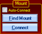
Auto-Connect - When this is checked, APCC will attempt to connect to the mount as a part of its start-up sequence. If you have this box checked, you will want to have an overall start-up procedure that powers the mount ON before starting APCC. This is common practice and is recommended in permanent and remote systems. Once connected, APCC will proceed through the initialization procedure you have previously defined.
NOTE Regarding Virtual Ports: If Virtual Ports are enabled and the first virtual port is set to "None" a com port will be automatically assigned to it. Starting with v1.5.0.9, this option will also select a virtual COM port for the first virtual port, if one hasn't been already defined. If you are using Virtual Com ports, we recommend that you enable this option. Starting with v1.5.0.14, this option will also select a second COM port for the second virtual port, if one hasn't been already defined. When used with the AP V2 ASCOM driver v 5.09.02, or later, this virtual port will be used by a driver that was started "As Administrator". This allows a user to mix ASCOM client applications that need to run "as administrator" with applications that are run normally. Two instances of the driver may appear simultaneously, both communicating independently with APCC. |
Connect/Disconnect Button - Click to connect APCC to the mount. The button will turn green to indicate successful connection. Click to Disconnect to disconnect from the mount, and the button will return to a blue color.
AP V2 Driver Sub-Group Box
This group box has one option: Config Driver. Pressing this button will configure the ASCOM driver with the correct settings for connecting to the mount via APCC.

Config Driver - When this is pressed, APCC will try a one-time configuration of the relevant sections of the AP V2 Driver's settings in order for the driver to connect properly.
If APCC determines the settings in the ASCOM V2 driver need to be updated, this button will display in a pink color. This indicates you should press this button and APCC will try to update the ASCOM settings. If it succeeds the button will turn back to blue, indicating it successfully updated the ASCOM driver connection settings

When the Config Driver button is Pink, this indicates the ASCOM driver and APCC settings are not consistent, and needs to be updated. Pressing this button resolves this issue.
ASCOM Connection to APCC via Client Applications
Once the ASCOM Driver connection details are finished, connection from ASCOM to APCC now is initiated by the client application (such as NINA, SGP, AP Jog Utility, etc.).
When the client application connects to the mount, it will launch the ASCOM driver, which then will connect to APCC. This process happens behind the scenes so it should just appear that the mount connects. "Pre Connecting" via APCC is no longer the preferred approach and is no longer supported in this version.