Run Tab

Contents
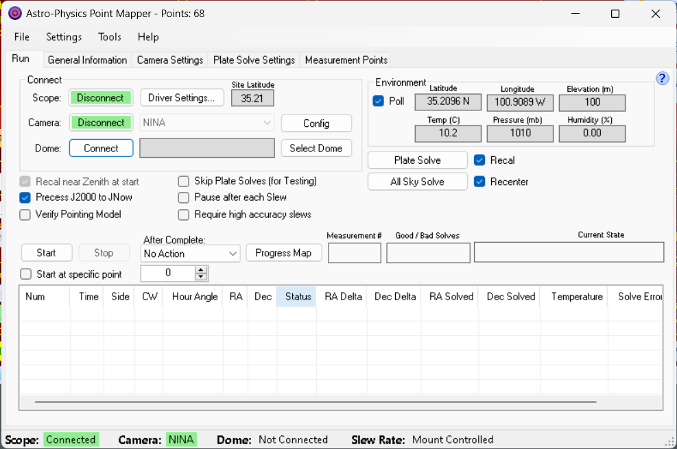
Connect Group Box
Scope: Press the Connect button to connect to the AP V2 ASCOM Driver. If you need to reconfigure the ASCOM AP V2 Driver click the Driver Settings... button.
Site Latitude: Shows the site latitude last retrieved from the AP V2 ASCOM Driver. This is available even when not connected to the mount and it is used by the "Show Points" window to properly display the location of the mapping model points. You must have connected to the mount once for the latitude to show in this box.
Camera: Select the camera type if needed then press the Connect button.
Supported camera types supported are listed below. All of the third-party applications can support many camera types, thus providing APPM with the capability of supporting many different cameras:
oMaxIm DL - A great third-party commercial imaging and camera control software application. Supports many third-party cameras. https://diffractionlimited.com
oCCDSoft - Another third party commercial camera control program. It is no longer supported but was shipped with SBIG cameras for many years.
oSkyX Pro Camera Add On - The successor to CCDSoft, it is part of TheSkyX Professional platform. Supports many third-party cameras. http://www.bisque.com/sc/pages/TheSkyX-Editions.aspx
oAstroArt - A relatively inexpensive commercial camera control program. Supports many third-party cameras. http://www.msb-astroart.com/
oASCOM Camera - Free camera drivers for some camera models. https://www.ascom-standards.org/Downloads/CameraDrivers.htm
oNINA - Great free image capture software. Supports many third-party cameras. - https://nighttime-imaging.eu/download/
NINA quick-start guide: https://daleghent.com/nina-and-astro-physics-mounts
oSequence Generator Pro - Great third-party image capture software. Supports many third-party cameras. - https://www.mainsequencesoftware.com/
oMeade DSI - DSI models 1-III are supported by APPM.
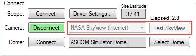
oNASA SkyView (Internet) - This is not a camera but a way to test the software during the day or when it is cloudy. It requires an internet connection to work. Images are taken from the DSS image If the scope/mount is not connected, clicking the Test SkyView button should download an image approximately centered on M33. However, when the mount is connected the image retrieved will be centered near the mount's RA/Dec coordinates.
You can collect test point data during the day by using NASA SkyView, but you don't want to load that data into APCC and use it at night because the data does not actually model the mount hardware.
More information about NASA SkyView can be found here: https://skyview.gsfc.nasa.gov
Dome: If you have a dome click the Select Dome button and select the ASCOM driver for your dome. Then click Connect to connect to the dome.
When using a dome APPM will slew both the mount and the dome to each target and wait for both to complete their slews before starting an exposure.
Please see this section in the Menus for additional dome settings.
Environment Group Box
This box shows the mount location and environmental conditions, if available.
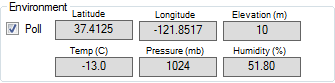
Poll: Enables polling of available properties from APCC via the ASCOM drive. The properties that are polled are Latitude, Longitude, Elevation, Temperature, Pressure, and Humidity.
If an ASCOM ObservingConditions driver or a THUM Temperature sensor is configured by APCC then environmental conditions for the device are displayed.
NOTE: If you are not using a THUM sensor or ASCOM ObservingConditions driver you can manually enter the current temperature and pressure on the Pointing Model tab in APCC.
Plate Solve, Recal, and Recenter
The options for plate solve, recal, and recenter have been revamped to offer more flexibility and capability compared to previous software releases. If you have used this feature before, we recommend you reread the following sections to familiarize yourself with the new updates:
Note: In order for the plate solve function to work, the Plate Solve Settings must be correctly configured prior to using this feature.
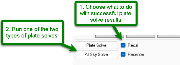
The workflow for plate solving and recal and/or recenter involves two steps:
1.First choose none, one or both of the optional checkboxes that determine what will happen next with successful plate solve results
2.Select and run a Plate Solve or All Sky Solve by clicking the relevant button
Recal: If the solve is successful, enabling Recal will recalibrate the mount's pointing position to the solved RA/Dec coordinates. This can be used whether APCC's Pointing and/or Tracking corrections are enabled or disabled. Recal is usually enabled so the mount's pointing position will be corrected and accurate for subsequent GoTos.
Recenter: When enabled, this option will then re-slew the mount to the original pointing position with the new updated coordinates. This works with either plate solve option, but Recal must be enabled for Recenter to work.
Plate Solve or All Sky Solve? Both options produce the same result, but does it in different ways. Both take an image and attempts to plate solve the image to find the true image center RA/Dec coordinates (The plate solved RA/Dec coordinates are converted to JNOW). Using Plate Solve option is best if you know your scope's pointing position is relatively close (roughly within 3-5 degrees). It also can solve relatively quickly, often within a few seconds. All Sky Solve is used when you are not confident in the accuracy of your scope's pointing position and may need to scan the entire sky to find the true pointing position. This can take many seconds to minutes and may require an Internet connection. All Sky Solve is typically not as accurate as Plate Solve. All Sky Solve is often used when first bringing up a new mount, or when attempting to troubleshoot a lost mount. Either Solve approach - if the solve is successful - will produce an accurate RA/Dec coordinate for your mount's pointing position
Here's an example to illustrate how these features work together: Let's say you did a GoTo to M31 Andromeda Galaxy which is at (rough) coordinates RA 0h43m Dec 41°23'. Next you used Plate Solve with Recal and Recenter options enabled. Plate Solve succeeds and determines the actual pointing position of your scope is RA 0h46m Dec 42°54'. Recal option updates the controller so now the mount correctly thinks it is pointing at the updated coordinates. Recenter issues a GoTo to M31 coordinates, which will move the scope from it's updated pointing position to M31, or approximately 3 minutes RA and 1°31' Dec.
Tip: Use APPM's Plate Solve and Recal function is often the best way to correctly establish the mount's pointing position for whatever reason. It is the most accurate, and it will never conflict with any of the corrections that are in effect from a model in APCC. It is the recommended way to calibrate your position before setting Home and Limits for encoder mounts |
Main Area
Recal near Zenith at Start: If checked, then when starting a new point mapping run, the scope will be slewed to near the zenith and an attempt made to recalibrate to a plate-solved image's RA/Dec coordinates. It is recommended that you keep this checked.
Precess J2000 to JNow: When checked the plate-solved coordinates are converted to JNow when stored in the log file, which might be useful for debugging purposes.
Verify Pointing Model: This option is used to test the quality of a model that you have already installed into APCC. If checked, a new pointing model is NOT generated. Instead, the currently loaded model is turned on in both pointing and tracking correction, and APPM will slew to the mapped points and check the pointing error at each point. This is often done on a much smaller, less dense point mapping than you would use to create a model. It is often also a good place to use the Model 5X and Park option in the After Complete drop down as described below. For example, you might want to run a 200 or 300 point mapping to create your actual model, and then test it by running 5 consecutive Verify mappings of 30 or 40 points each. Running the same verify mapping 5 times will show the repeatability of the model's corrections.
Skip Plate Solves (for Testing): If checked images will be taken but not plate solved. This option would be used to check telescope operations. This option is not saved between invocations of APPM.
Pause after each Slew: The purpose of this is to allow you to do some action(s) before plate solving, such as manually moving a dome into position before proceeding. After each slew the status table will show a state of "Paused", allowing you to do actions. To continue you must click the "Restart" button. This is the same button as "Start" but it's name will have been changed to "Restart" when paused. When restarted APPM will start off with a very short re-slew to the current mapping point, do the plate solve, and then slew to the next point. At that time it will pause again.
Note that if you need to use the "Pause after each Slew" option it must be checked every time you run APPM. The Pause after each Slew option is not saved.
Start: Starts a mapping run. Once clicked the button changes to Pause, which will allow you to pause the scope as needed. When paused, the button will read Restart.
Stop: Stops a mapping run. This permanently aborts the mapping run.
After Complete: this setting determines what happens after the modeling run completes. Choices include No Action, Stop Tracking, Park, and Model 5x and Park.
oNo Action - When the mapping run is completed, the scope remains pointed at the last RA / Dec coordinate from the mapping run. Sidereal tracking continues. DO NOT choose this option if you plan to leave a mapping run unattended.
oStop Tracking - When the mapping run is completed, the scope remains pointed at the last Alt / Az coordinate from the mapping run. Sidereal tracking is stopped.
oPark - When the mapping run is completed, the mount is parked to the park position selected in the AP V2 ASCOM Driver.
oModel 5x and Park - This option runs 5 consecutive, individual mapping runs. It is meant to be used with the Verify Pointing Model option described above.
Measurement #: Indicates the current measurement point when active. If you are running Windows 7 or later the Task Bar icon will also indicate progress with a green progress overlay.
Good/Bad Solves: Indicates the number of good and bad plate solves.
Current State: Indicates the current state machine state.
Start as specific point: generally used only for debugging. When checked and Start is clicked the scope will immediately skip to the entered point number.You cannot use this feature to re-do portions of a mapping run.
Table: This table provides feedback for each measured point.